
Software Companions XML Markup Format Description
The Software Companions XML markup format can be easily created by using a text editor. You can also export XML files from ViewCompanion.
By using this format you can create easily your own custom markup files from scratch.
In ViewCompanion you can use XML formatted markup files in combination with the command line
parameter /lxml during command line conversion and printing.
You may also load XML markup files from inside the application by using the "Add From File" menu command or add it during batch conversion.
If you're using scViewerX you can load XML markup files using the MarkupAddFromFile method.
To load XML data already in memory (as string) you can use the MarkupCreateFromXML method.
The default extension for a Software Companions XML Markup file is .scmx, but .xml may also be used.
File Format Specification
The file must start with the following header:
<SCMarkupFormat>
Only UTF-8 encoding is currently supported.
The header and elements section then follows.
A complete sample xml markup file is shown below:
<SCMarkupFormat>
<Header>
<Unit>mm</Unit>
</Header>
<Layers>
<layer name="Markup Layer 1" color="#0000FF" enabled='1'/>
<layer name="Markup Layer 2" color="#00FF00" enabled='1'/>
</Layers>
<Elements>
<Element>
<type>Text</type>
<layer>0</layer>
<page>0</page>
<center x="50%" y="50%"/>
<user>Peter</user>
<color>#FF0000</color>
<text>This is a text</text>
<rotation>45</rotation>
<font height='10' facename='Times New Roman'/>
</Element>
</Elements>
</SCMarkupFormat>
This xml markup file defines a single text element. The text center position is at 50% of document width and 50% of document height.
The markup coordinate system origin is always the lower left corner of the drawing.
The coordinates can be given in millimeters, inches or native (1016 DPI) values.
All color values are coded as red, green and blue intensities in hexadecimal notation (HTML standard - #RRGGBB).
The Layers section defines two layers.
You will find more information about the different sections below.
Header Section
This section contains settings that are common for all markup elements.
The available entries in this section are:
Unit
Accepted values:
| Value | Description |
| mm | Coordinates and sizes are given in millimeters. |
| inch | Coordinates and sizes are given in inches. |
| mil | Coordinates and sizes are given in 1/1000 inch. |
| native | Coordinates and sizes are given in native coordinates (1016 DPI). |
This section is required.
Layers Section
This section contains markup layer definitions. Each layer definition can have three different attributes.
The first defined layer will have index 0, the next one 1, etc. The layer index is used when elements are defined.
The description of each layer attribute is given below:
| Attribute Name | Description |
| Name | Name to use for the layer. |
| Color | Default color to use for elements placed on this layer. |
| Enabled | Enter a value different from 0 to make the layer visible. |
Sample layer defintion:
This sample xml defintion will create a layer that is named "Markup Layer 1", with default color blue and it will be visible and enabled.
Please note that the layers section is optional, and is only required if you want to add more than one layer of markups.
Elements Section
This section contains one or more Element entries.
See description of each available Element type below.
Element Section
Each element section defines a new markup element, also know as an annotation or comment.
Some of the keywords are common for all element types, and some are type specific.
The following table lists the keywords that are common for all elements:
| Keyword | Description |
| type | Markup element type keyword. The following element types are available: Arrow Barcode Circle Ellipse Erase Polygonal Area Erase Rectangular Area Eraser Line Picture Polygon Polyline Rectangle Revision Cloud Rounded Rectangle Rubber Stamp Shape Symbol Text |
| handle | A unique numerical ID to be applied to the element. If not provided an ID will be automatically provided. |
| hyperlink | Link to a document or an URL. |
| layer | Layer index to use for the markup element. Layer indexes are zero based. |
| locked | Set the element lock flag. A locked element (non zero value) cannot be moved or modified. |
| page | Page index where the markup element will be placed. Page indexes are zero based. If you set the page index to -1 the element will be visible on all pages in the document. |
| transparent | If defined, the markup element will be transparent. |
| user | Name of the user that have created the element. If an user name is not provided the name of the currently logged in user will be used. |
Arrow Element
The arrow element requires the following keywords, in addition to the common keywords:
| Keyword | Description |
| points | This section contains one point entry for each point in the arrow polyline. Each point is defined with an x and y attribute. See the xml definition below for an example on how to describe point entries. |
| color | Define draw color to use for the element. |
| arrowhead | Define type of arrow header to use. Supported arrow types: 0: open, 1: closed, 2: filled. |
| arrowsize | Define size of arrow header. |
| linewidth | Define width of the arrow lines. The width is defined using the active unit. This entry is optional. |
Sample arrow element xml definition:
<type>Arrow</type>
<layer>0</layer>
<page>0</page>
<color>#FF0000</color>
<arrowhead>2</arrowhead>
<arrowsize>5</arrowsize>
<linewidth>0.3</linewidth>
<points>
<point x='100' y='100'/>
<point x='150' y='150'/>
<point x='200' y='150'/>
</points>
</element>
This xml data will create the following arrow:
Barcode Markup Element
Create a barcode element. Please note that if you later save the markup, a barcode element will be saved as a symbol element.
The barcode element definition uses the following keywords, in addition to the common keywords:
| Keyword | Description |
| center | Barcode center coordinates. The center coordinate is defined by setting x and y to a percentage of the document extents, or absolute values. Sample usages: <center x="50%" y="50%"/> Add the barcode centered at document center. <center x="50%" y="40"/> Add the barcode horizontally centered and 40 millimeters above the bottom of the page. |
| size | Set the dimensions for the barcode in percentage of current document extents, or absolute values. The extents are defined using two attributes named w and h. Sample definitions: <size w="10%" y="10%"/> Create a barcode with width equal to 10% of document page width, and the height will be 10% of document page height. <size w="40" y="40"/> Create a barcode with width and height set to 40 units. |
| barcodetype | The type of barcode encoder to use. The following barcode standards are supported:
|
| barcodeincludetext | Include the actual text as part of the barcode image. |
| barcodelabel | Optional label text added to the barcode image. |
| imagerotation | Set image rotation to use for the barcode image. The following rotation factors are supported:
|
| text | The text to encode using the selected barcode type. |
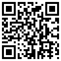
Sample barcode element definition using absolute coordinates:
<type>Barcode</type>
<barcodetype>QR</barcodetype>
<layer>0</layer>
<page>0</page>
<center x="50%" y="40"/>
<size w="40" h="40"/>
<text>http://www.gerbview.com</text>
</element>
This xml definition will create the following barcode element:
Circle Element
The circle element requires the following keywords, in addition to the common keywords:
| Keyword | Description |
| center |
Circle center coordinates. The center coordinate is defined by setting x and y to a percentage of the document extents, or absolute values. Sample usages: <center x="50%" y="50%"/> Add the circle centered at document center. <center x="50%" y="40"/> Add the circle horizontally centered and 40 millimeters above the bottom of the page. |
| radius | Radius of circle. |
| fillcolor | Define fill color to use for the element. |
| color | Define outline color to use for the element. |
| linewidth | Define width of the outline. The width is defined using the active unit. This entry is optional. |
| linestyle | Define line style to use for the outline. This entry is optional. |
| fillstyle | Define fill style to use for the element. This entry is optional. |
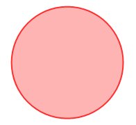
Sample circle element xml definition:
<type>Circle</type>
<layer>0</layer>
<page>0</page>
<center x="50%" y="40"/>
<radius>50</radius>
<color>#FF0000</color>
<fillcolor>#FFA0A0</fillcolor>
<fillstyle>1</fillstyle>
<linewidth>1.0</linewidth>
<transparent/>
</element>
This xml definition will create the following circle:
Ellipse Element
The ellipse element uses the following keywords, in addition to the common keywords:
| Keyword | Description |
| boundary |
Define boundary for the created ellipse. The boundary is defined using four attributes. These attributes are named: x1, y1, x2 and y2. Sample boundary entry: <boundary x1='80' x2='180' y1='10' y2='110'/> |
| fillcolor | Define fill color to use for the element. |
| color | Define outline color to use for the element. |
| linewidth | Define width of the outline. The width is defined using the active unit. This entry is optional. |
| linestyle | Define line style to use for the outline. This entry is optional. |
| fillstyle | Define fill style to use for the element. This entry is optional. |
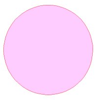
Sample ellipse element xml definition:
<type>Ellipse</type>
<layer>0</layer>
<page>0</page>
<boundary x1='80' x2='200' y1='10' y2='110'/>
<color>#FF0000</color>
<fillcolor>#FFCCFF</fillcolor>
<fillstyle>1</fillstyle>
<linewidth>1.0</linewidth>
<transparent/>
</element>
This xml data will create the following ellipse:
Erase Polygonal Area
Define an area to hide (erase) using a polygon. This feature is also known as wipeout.
The erase polygonal area element requires the following keywords, in addition to the common keywords:
| Keyword | Description |
| points |
This section contains one point entry for each point in the polygon. Each point is defined with an x and y attribute. See the xml definition below for an example on how to define the point entries. |
Sample erase polygonal area element xml definition:
<type>Erase Polygonal Area</type>
<layer>0</layer>
<page>0</page>
<points>
<point x='150' y='190'/>
<point x='150' y='290'/>
<point x='200' y='290'/>
<point x='200' y='265'/>
<point x='175' y='265'/>
<point x='175' y='215'/>
<point x='200' y='215'/>
<point x='200' y='190'/>
<point x='150' y='190'/>
</points>
</element>
This xml data will erase the polygonal area as shown below when used for sample file compare_revA.plt:
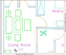
Before xml markup is loaded
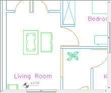
After xml markup is loaded
Erase Rectangular Area
Define an area to hide (erase) using a rectangle. This feature is also known as wipeout.
The erase rectangular area element requires the following keywords, in addition to the common keywords:
| Keyword | Description |
| boundary | Define boundary for the created rectangle. The boundary is defined using four attributes. These attributes are named: x1, y1, x2 and y2. Sample boundary entry: <boundary x1='150' x2='190' y1='230' y2='290'/> |
Sample erase rectangular area element xml definition:
<type>Erase Rectangular Area</type>
<layer>0</layer>
<page>0</page>
<boundary x1='150' y1='190' x2='230' y2='290'/>
</element>
This xml definition will erase the rectangular area as shown below when used for sample file compare_revA.plt:
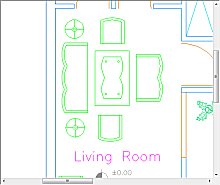
Before xml markup is loaded
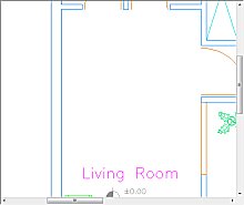
After xml markup is loaded
Eraser
Define a polyline that will erase/hide drawing contents. This is known as the freehand eraser in ViewCompanion.
The polyline defined will be drawn with the current background color and with the width defined by the linewidth setting.
The eraser element requires the following keywords, in addition to the common keywords:
| Keyword | Description |
| points | This section contains one point entry for each point in the polyline. Each point is defined with an x and y attribute. See the xml definition below for an example on how to describe point entries. |
Sample eraser element xml definition:
<type>Eraser</type>
<layer>0</layer>
<page>0</page>
<linewidth>5.0</linewidth>
<points>
<point x='150' y='190'/>
<point x='150' y='290'/>
<point x='200' y='290'/>
<point x='200' y='265'/>
<point x='175' y='265'/>
<point x='175' y='215'/>
<point x='200' y='215'/>
<point x='200' y='190'/>
</points>
</element>
Line Element
The line element uses the following keywords, in addition to the common keywords:
| Keyword | Description |
| boundary | Define boundary for the created line. The boundary is defined using four attributes. These attributes are named: x1, y1, x2 and y2. Sample boundary entry: <boundary x1='80' x2='180' y1='10' y2='110'/>. The line will be drawn between x1,y1 and x2,y2. |
| color | Define line color to use for the element. |
| linewidth | Define the width of the line. The width is defined using the active unit. This entry is optional. |
| linestyle | Define line style to use for the line. This entry is optional. |
Sample line element xml definition:
<type>Line</type>
<layer>0</layer>
<page>0</page>
<boundary x1='80' x2='180' y1='10' y2='110'/>
<color>#00FF00</color>
<linewidth>1.0</linewidth>
<linestyle>0</linestyle>
</element>
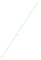
This xml defintition will create the following line:
Picture Element
The picture element uses the following keywords, in addition to the common keywords:
| Keyword | Description |
| center | Picture center coordinates. The center coordinate is defined by setting x and y to a percentage of the document extents, or using absolute values. Sample usages: <center x="50%" y="50%"/> Add the picture centered at document center. <center x="50%" y="50"/> Add the picture horizontally centered and 50 millimeters above the bottom of the page. |
| filename | The full path to the picture file that will be added as a markup element. Please note that either double back slash (\\), or a single slash (/) must be used. If the picture file is located in the same folder as the XML file, you only need to include the file name. |
| imagerotation | Rotation in degrees that should be applied to the picture. The following rotation values are valid: 0, 90, 180 and 270. |
| size | Set the dimensions for the picture in percentage of current document extents, or using absolute values. If you do not specify the size, the actual image dimensions will be used, based on the image file dpi (resolutin). The dimensions are defined using two attributes named w and h. Sample definitions: <size w="10%" h="10%"/> Add the picture with width equal to 10% of document page width, and the height will be 10% of document page height. <size w="40" h="40"/> Add the picture with width and height set to 40 units. |
Sample picture element xml definition:
<type>Picture</type>
<layer>0</layer>
<page>0</page>
<center x="50%" y="50%"/>
<size w="25%" h="10%"/>
<filename>logo.jpg</filename>
</element>
This xml definition will add the following picture:

Polygon Element
The polygon element requires the following keywords, in addition to the common keywords:
| Keyword | Description |
| points | This section contains one point entry for each point in the polygon. Each point is defined with an x and y attribute. See the polygon element definition below for an example on how to describe point entries. |
| color | Define line color to use for the element. |
| fillcolor | Define fill color to use for the element. |
| color | Define outline color to use for the element. |
| linewidth | Define width of the outline. The width is defined using the active unit. This entry is optional. |
| fillstyle | Define fill style to use for the element. This entry is optional. |
Sample polygon element xml definition:
<type>Polygon</type>
<layer>0</layer>
<page>0</page>
<color>#FF0000</color>
<fillcolor>#CCFFCC</fillcolor>
<linewidth>0</linewidth>
<fillstyle>1</fillstyle>
<points>
<point x='10' y='10'/>
<point x='20' y='20'/>
<point x='30' y='10'/>
<point x='20' y='0'/>
</points>
</element>
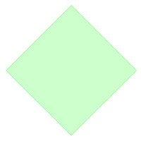
This xml definition will create the following 4-point polygon:
Polyline Element
The polyline element requires the following keywords, in addition to the common keywords:
| Keyword | Description |
| points | This section contains one point entry for each point in the polyline. Each point is defined with an x and y attribute. See the polyline element definition below for an example on how to describe point entries. |
| color | Define line color to use for the element. |
| fillcolor | Define fill color to use for the element. |
| color | Define outline color to use for the element. |
| linewidth | Define width of the polyline. The width is defined using the active unit. This entry is optional. |
| linestyle | Define line style to use for the outline. This entry is optional. |
Sample polyline element xml definition:
<type>Polyline</type>
<layer>0</layer>
<page>0</page>
<color>#FF0000</color>
<linewidth>0.5</linewidth>
<points>
<point x='10' y='10'/>
<point x='15' y='15'/>
<point x='20' y='10'/>
<point x='25' y='15'/>
</points>
</element>
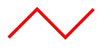
This xml definition will create the following polyline:
Rectangle Element
The rectangle element requires the following keywords, in addition to the common keywords:
| Keyword | Description |
| boundary | Define boundary for the created rectangle. The boundary is defined using four attributes. These attributes are named: x1, y1, x2 and y2. Sample boundary entry: <boundary x1='80' x2='180' y1='10' y2='110'/> |
| fillcolor | Define fill color to use for the element. |
| color | Define outline color to use for the element. |
| linewidth | Define width of the outline. The width is defined using the active unit. This entry is optional. |
| fillstyle | Define fill style to use for the element. This entry is optional. |
Sample rectangle element xml definition:
<type>Rectangle</type>
<layer>0</layer>
<page>0</page>
<boundary x1='10' x2='100' y1='110' y2='200'/>
<color>#0000FF</color>
<fillcolor>#00CCFF</fillcolor>
<fillstyle>1</fillstyle>
<linewidth>0</linewidth>
<transparent/>
</element>
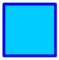
The xml data to the left will create the following rectangle:
Revision Cloud Element
The revision cloud element requires the following keywords, in addition to the common keywords:
| Keyword | Description |
| boundary | Define boundary for the created revision cloud. The boundary is defined using four attributes. These attributes are named: x1, y1, x2 and y2. Sample boundary entry: <boundary x1='80' x2='180' y1='10' y2='110'/> |
| fillcolor | Define fill color to use for the element. |
| color | Define outline color to use for the element. |
| linewidth | Define width of the outline. The width is defined using the active unit. This entry is optional. |
| fillstyle | Define fill style to use for the element. This entry is optional. |
| arclimit | Set the maximum size of radius for each arc used to create the revision cloud. This entry is optional. |
Sample revision cloud element xml definition:
<type>Revision Cloud</type>
<layer>0</layer>
<page>0</page>
<boundary x1='50' x2='150' y1='210' y2='250'/>
<color>#FF0000</color>
<fillstyle>0</fillstyle>
<linewidth>3</linewidth>
<transparent/>
</element>
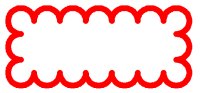
This xml definition will create the following revision cloud:
Rounded Rectangle Element
The rounded rectangle element requires the following keywords, in addition to the common keywords:
| Keyword | Description |
| boundary | Define boundary for the created rounded rectangle. The boundary is defined using four attributes. These attributes are named: x1, y1, x2 and y2. Sample boundary entry: <boundary x1='80' x2='180' y1='10' y2='110'/> |
| fillcolor | Define fill color to use for the element. |
| color | Define outline color to use for the element. |
| linewidth | Define width of the outline. The width is defined using the active unit. This entry is optional. |
| fillstyle | Define fill style to use for the element. This entry is optional. |
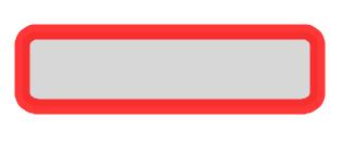
Sample rectangle element xml definition:
<type>Rounded Rectangle</type>
<layer>0</layer>
<page>0</page>
<boundary x1='50' x2='90' y1='50' y2='60'/>
<color>#FF0000</color>
<fillcolor>#CCCCCC</fillcolor>
<fillstyle>1</fillstyle>
<linewidth>2</linewidth>
<transparent/>
</element>
This xml definition will create the following element:
Rubber Stamp Element
The rubber stamp element definition method uses the following keywords, in addition to the common keywords:
| Keyword | Description |
| center |
Define center point for the rubber stamp in percentage of document extents, or using absolute coordinates. The center point is defined using two attributes and these are named x and y.
Sample definitions: <center x="50%" y="50%"/> This will place the stamp centered on the document page. <center x="100" y="100"/> This will place the stamp with center 100 millimeters from the left and 100 millimeters above the bottom of the page. |
| size |
Set the extents for the rubber stamp in percentage of current document page extents, or absolute values.
The extents are defined using two attributes named w and h. Sample definitions: <size w="20%" y="10%"/> This will create a stamp with width equal to 20% of document page width, and the height will be 10% of document page height. <size w="80" y="20"/> This will create a stamp with width of 80 units and height of 20 units. |
| backcolor | Define stamp background color. |
| textcolor | Define color to use for the stamp text. |
| text | Stamp text. |
| font | Define font to use for the stamp text. The font is defined using several different attributes, each of them correspond to the Windows LOGFONT definition. The following font attributes are supported: height - Same as LOGFONT lfHeight. Please note that this value will be recalculated. orientation - Same as LOGFONT lfOrientation. weight - Same as LOGFONT lfWeight. italic - Same as LOGFONT lfItalic. underline - Same as LOGFONT lfUnderline. strikeout - Same as LOGFONT lfStrikeout. charset - Same as LOGFONT lfCharset. outprecision - Same as LOGFONT lfOutPrecision. clipprecision - Same as LOGFONT lfClipPrecision. quality - Same as LOGFONT lfQuality. pitch - Same as LOGFONT lfPitchAndFamily. facename - Same as LOGFONT lfFaceName. Sample font definition: <font italic='1' facename='Times New Roman'/> |
| linewidth | Define width of the outline. The width is defined using the active unit. This entry is optional. |
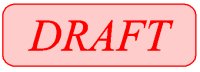
Sample rubber stamp element definition:
<type>Rubber Stamp</type>
<layer>0</layer>
<page>0</page>
<center x="50%" y="50%"/>
<size w="20%" h="10%"/>
<text>Draft</text>
<textcolor>#FF0000</textcolor>
<backcolor>#FFCCCC</backcolor>
<font italic='0' facename='Times New Roman'/>
<transparent/>
</element>
The xml data to the left will create the following rubber stamp:
Shape Element
The shape element requires the following keywords, in addition to the common keywords:
| Keyword | Description |
| center |
The center coordinate is defined by setting x and y to a percentage of the document extents, or absolute values. Sample usages: <center x="50%" y="50%"/> Add the shape centered at document center. <center x="50%" y="40"/> Add the shape horizontally centered and 40 millimeters above the bottom of the page. |
| shapetype |
One of the predefined shape types:
|
| shapesize | Size of the shape element in current units. |
Sample shape element definition:
<type>Shape</type>
<page>0</page>
<center x="50%" y="50%"/>
<shapetype>0</shapetype>
<shapesize>10</shapesize>
</element>
This xml defintion will add the following symbol to the document:

Symbol Markup Element
The symbol element requires the following keywords, in addition to the common keywords:
| Keyword | Description |
| boundary | Define boundary for the created symbol. The boundary is defined using four attributes. These attributes are named: x1, y1, x2 and y2. Sample boundary entry: <boundary x1='100' x2='150' y1='200' y2='250'/> |
| symbollibrary | The name of the symbol library to use. |
| symbolname | The name of the symbol to use. |
Sample symbol element definition:
<type>Symbol</type>
<layer>0</layer>
<page>0</page>
<boundary x1='100' x2='150' y1='100' y2='150'/>
<symbollibrary>Sample</symbollibrary>
<symbolname>Copyright</symbolname>
</element>
This xml definition will add the following symbol to the document:

The Sample symbol library used in this example is included in the ViewCompanion installation.
Text Markup Element
The text element requires the following keywords, in addition to the common keywords:
| Keyword | Description |
| center |
Text center coordinate. Text center coordinate is defined by setting x and y to a percentage of the document extents, or absolute coordinates. Sample usage: <center x="50%" y="50%"/> This will add the text centered at document center. <center x="100" y="20"/> This will add the 100 millimeters from the left and 20 millimeters above the bottom of the page. |
| insertx |
Text insert x coordinate. This value is the absolute coordinate for the horizontal text origin. You may also use
percentage of the document width, for example:
<insertx>50%</insertx> You must use either text center as described above or insertx together with inserty to define the text origin. |
| inserty |
Text insert y coordinate. This value is the absolute coordinate for the vertical text origin.
You may also use percentage of the document height, for example:
<inserty>50%</inserty> You must use either text center as described above or inserty together with insertx to define the text origin. |
| alignment |
The alignment setting defines the origin of the text to insert. Please note that this setting can only be used together with the insertx and inserty keywords. The following values are available:
|
| rotation | Text rotation in degrees. |
| textcolor | Define color to use for the text. |
| text | The text string to display. |
| font | Define font to use for the text. The font is defined using several different attributes, each of them correspond to the Windows LOGFONT definition. The following font attributes are supported: height - Same as LOGFONT lfHeight. width - Samer as LOGFONT lfWidth. orientation - Same as LOGFONT lfOrientation. weight - Same as LOGFONT lfWeight. italic - Same as LOGFONT lfItalic. underline - Same as LOGFONT lfUnderline. strikeout - Same as LOGFONT lfStrikeout. charset - Same as LOGFONT lfCharset. outprecision - Same as LOGFONT lfOutPrecision. clipprecision - Same as LOGFONT lfClipPrecision. quality - Same as LOGFONT lfQuality. pitch - Same as LOGFONT lfPitchAndFamily. facename - Same as LOGFONT lfFaceName. Sample font definition: <font italic='1' facename='Times New Roman'/> |
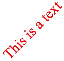
Sample text element definition:
<type>Text</type>
<layer>0</layer>
<page>0</page>
<center x="50%" y="50%"/>
<textcolor>#FF0000</textcolor>
<text>This is a text</text>
<rotation>45</rotation>
<font height='10' facename='Times New Roman'/>
</element>
The xml data to the left will create the following text element:
Line and Fill Style Values
Line style
The line style can be one of the following values:
- Solid line
- Dashed line
- Dotted line
- Dash-dot line
- Dash-dot-dot line
Fill style
The fill style can be one the following values:
- Outlined (no fill)
- Solid fill
- Horizontal hatch lines
- Vertical hatch lines
- Crosshatched lines
- Diagonal hatch lines
- Diagonal cross hatch lines
|


